

আগের পর্বে আমরা পাওয়ার ট্রান্সফরমার ও তার কার্যপ্রণালী সম্পর্কে কিছু প্রাথমিক আলোচনা করেছিলাম, এ পর্বে আমরা দেখবো কিভাবে আয়রণ কোর পাওয়ার ট্রান্সফরমারের সর্বোচ্চ আউটপুট পাওয়ার হিসাব করা যায়, এবং কিভাবে কয়েলের জন্য তারের পাকসংখ্যা হিসাব করা যায়।
পরিচ্ছেদসমূহ
- 1 হিসাবপ্রণালী (Calculation)
- 2 ট্রান্সফরমার তৈরি করবার একটি উদাহরণ:
- 3 সমাধান:
- 3.1 ১ম ধাপ: সর্বমোট আউটপুট পাওয়ার নির্ণয়
- 3.2 ২য় ধাপ: কোরের প্রস্থচ্ছেদের ক্ষেত্রফল নির্ণয়
- 3.3 ৩য় ধাপ: ইনপুট পাওয়ার নির্ণয়
- 3.4 ৪র্থ ধাপ: প্রাইমারী কয়েলের কারেন্ট নির্ণয়
- 3.5 সতর্কতা:
- 3.6 ৫ম ধাপ: N নির্ণয়
- 3.7 ৬ষ্ট ধাপ: কয়েলের জন্য তারের পাকসংখ্যা হিসাব
- 3.8 ৭ম ধাপ: তারের গেজ নির্ণয়
- 3.9 প্রাইমারী কয়েল
- 3.10 সেকেন্ডারী কয়েল
- 3.11 পরিশেষে বলা যায়
- 4 সমাপ্তি
হিসাবপ্রণালী (Calculation)
১ম ধাপ: কোরের ক্ষেত্রফল নির্ণয়
নিম্নোক্ত সূত্র অনূযায়ী কোরের প্রস্থছেদের ক্ষেত্রফল হিসাব করা হয়:
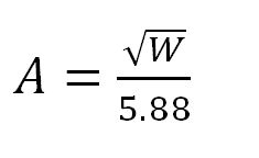
এখানে W হলো ভোল্ট-এম্পিয়ারে (VA) তে ট্রান্সফরমারের আউটপুট পাওয়ারের পরিমান এবং A হলো স্কয়ার ইঞ্চিতে কোরের প্রস্থছেদের ক্ষেত্রফল
উপরের সমীকরণ থেকে লেখা যায়
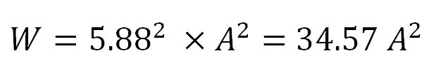
একটি ট্রান্সফরমার সর্বোচ্চ কতো পাওয়ার আউটপুট দিতে পারবে, তা উপরের সমীকরণের সাহায্যে হিসাব করা যায়।
২য় ধাপ: N নির্ণয়
পরবর্তিধাপে আমাদের ট্রান্সফরমারের Number of Turns per Volt (N দিয়ে প্রকাশ করা হয়) হিসাব করতে হবে। কয়েলের প্রতিটি টার্ন বা প্যাচে কত ভোল্ট উৎপন্ন হবে, তা Number of Turns per Volt থেকে বোঝা যায়। নিম্নোক্ত সূত্র অনূযায়ী Number of Turns per Volt হিসাব করা হয়:
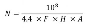
এখানে N হলো Number of Turns per Volt
F হলো ইনপুট ফ্রিকুয়েন্সি (হার্জ বা Hz এককে)
H হলো কোরের প্রতি স্কয়ার ইঞ্চিতে ম্যাগনেটিক ফ্লাক্স-এর সর্বোচ্চ লাইন সংখ্যা
এবং A কোরের প্রস্থছেদের ক্ষেত্রফল
ট্রান্সফরমার তৈরি করবার একটি উদাহরণ:
এমন একটি পাওয়ার ট্রান্সফরমার ডিজাইন করতে হবে, যাতে নিচের বৈশিষ্ট্য গুলো থাকবে।
- Primary = 220 V
- Secondary:
- 350 V at 120 mA
- 6.3 V at 3 A
- 5 V at 2.2 A
সমাধান:
১ম ধাপ: সর্বমোট আউটপুট পাওয়ার নির্ণয়
- 350 V x 120 mA = 42 Watts
- 6.3 V x 3 A = 18.9 Watts
- 5 V x 2.2 A = 11 Watts
Total = 71.9 Watts = 72 Watts
২য় ধাপ: কোরের প্রস্থচ্ছেদের ক্ষেত্রফল নির্ণয়
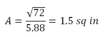
নিরাপত্তার খাতিরে এই ফলাফলের সাথে আরও 0.3 Square Inch যোগ করলে মোট ক্ষেত্রফল দাড়ায় A = 1.8 sq In.
৩য় ধাপ: ইনপুট পাওয়ার নির্ণয়
ধরা যাক, ট্রান্সফরমারটি ৯০% এফিসিয়েন্ট হবে, অর্থাৎ ইনপুটে ১০০ ওয়াট দিলে আউটপুটে ৯০ ওয়াট পাওয়া যাবে। সেক্ষেত্রে,
সর্বমোট আউটপুট পাওয়ার 72 Watts
তাহলে ইনপুট পাওয়ার হবে

অর্থাৎ 80 Watts ইনপুট দিলে আউটপুটে 72 Watts পাওয়া যা্বে
৪র্থ ধাপ: প্রাইমারী কয়েলের কারেন্ট নির্ণয়
যেহেতু প্রাইমারিতে 80 Watts ইনপুট দেয়া হবে, সেহেতু 220V এ প্রাইমারিতে ইনপুট কারেন্ট হবে 80/220 = 0.36A ।এক্ষেত্রে প্রাইমারি সাইডে কয়েলের জন্য এমনভাবে তার নির্বাচন করতে হবে, যেনো তা নিরাপদে এই পরিমান কারেন্ট প্রবাহিত করতে পারে।
সতর্কতা:
তার নির্বাচনের সময় লক্ষ রাখতে হবে যেনো, তারের এনামেল কোটিং এ কোনো প্রকার, কাটা-ছেড়া, ঘষা-মাজা না থাকে। কয়েলের কোনো একটি প্যাচের যদি সামান্য অংশেরও ইনস্যুলেশন নষ্ট হয়ে যায়, তো সেটা পুরো ট্রান্সফর্মারকেই অকেজো করে দিতে পারে।
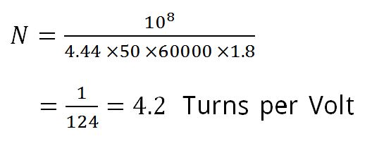
৫ম ধাপ: N নির্ণয়
আমাদের ক্ষেত্রে ইনপুট EMF এর ফ্রিকুয়েন্সি F = 50 Hz
H বা flux density এর মান সাধারণভাবে প্রতি Squire Inch এ 60,000 লাইন ধরা হয়।
এছাড়া পূর্বের হিসাব অনুযায়ী A = 1.8 sq in
তাহলে,
৬ষ্ট ধাপ: কয়েলের জন্য তারের পাকসংখ্যা হিসাব
প্রাইমারী কয়েলের জন্য 220 X 4.2 = 924 পাক
সেকেন্ডারী কয়েলের জন্য
- 350 x 4.2 = 1470 পাক
- 6.3 x 4.2 = 26.5 পাক
- 5 x 4.2 = 21 পাক
৭ম ধাপ: তারের গেজ নির্ণয়
নিরাপত্তার কারণে এধরনের ট্রান্সফর্মারের জন্য প্রতি বর্গইঞ্চিতে প্রবাহিত কারেন্টের মাত্রা ২০০০ এম্পিয়ার ধরা হয়। অর্থাৎ SWG Table এর নির্দিষ্ট কলামের (১৪ নাম্বার কলাম) ভ্যালুকে ২ গুণ করে, অথবা কারেন্ট রেটিংকে (যা সূত্রানুসারে পাওয়া গেছে) অর্ধেক করে চার্ট থেকে তারের গেজ নির্ণয় করতে হবে।
")
প্রাইমারী কয়েল
এ ক্ষেত্রে 0.36A (৪র্থ ধাপ অনুযায়ী), সুতরাং সূত্র মতে 0.18A (Half current rating) কে SWG Table এর ১৪ নং কলামে খুজে দেখলে সেটি অথবা এর কাছাকাছি তারের যে গেজ নাম্বারটি পাওয়া যায়, সেটিই ব্যাবহার করতে হবে। এক্ষেত্রে হবে ২৭ নং তার যা 0.18A কারেন্ট ভালোভাবেই পরিবহনে সক্ষম।
(টেবিল খেয়াল করলে দেখা যাবে এ তারটি সর্বচ্চো 0.21A কারেন্ট পরিবহন করতে পারে।)
সুতরাং প্রাইমারি কয়েলটি enamel এবং single silk কভারিং যুক্ত 27 SWG তার দিয়ে তৈরি করতে হবে।
সেকেন্ডারী কয়েল
- HT 350V কয়েলে 120 mA কারেন্ট প্রবাহিত হয়। এর অর্ধেক করলে দাড়ায় 60 mA বা 0.06A। টেবিল থেকে এই কারেন্টের জন্য উপযোগী তার খুজলে দেখা যায় 34 SWG তার এই পরিমাণ কারেন্ট নিরাপদে প্রবাহিত করতে পারে।
- Heater windings: এই কয়েল দিয়ে ২ থেকে ৩ এম্পিয়ার কারেন্ট প্রবাহিত হয়, যার অর্ধেক ১ থেকে ১.৫ এম্পিয়ার। টেবিল থেকে দেখা যায় 18 SWG তার এর জন্য উপযুক্ত।
পরিশেষে বলা যায়
- Primary winding: 27 SWG 924 turns
- Secondary windings:
- HT = 34 SWG 1050 turns
- Heaters
- 18 SWG 26.5 turns
- 18 SWG 21 turns
সমাপ্তি
আজ এ পর্যন্তই। পরবর্তীতে এই উদাহরণের ট্রান্সফরমারটির নির্মাণ কৌশল এবং 300VA ও 500VA ট্রান্সফরমারের জন্যও একটি করে উদাহরণ দেয়ার চেষ্টা করবো। ততক্ষণ পর্যন্ত আমাদের সাথেই থাকুন। কোনো প্রশ্ন থাকলে বা কোনো ভূলত্রুটি থাকলে নিচে কমেন্টস বক্স ব্যবহার করুন, চাইলে আমাদের ফেসবুক পেজ থেকেও ঘুরে আসতে পারেন। ধন্যবাদ।
মূল প্রবন্ধ: Build Your Own Coils and Transformers
প্রকাশক: BPB Publications
অনুবাদ: শুকদেব বিশ্বাস
বিশেষ কৃতজ্ঞতা: Shoaib Hossain
সার্বিক সহযোগিতায়: সৈয়দ রাইয়ান


heater coil bishoy ta bujhlam na
আগের পোষ্টে বলা হয়েছে কোরের সাথে কয়েল সাইজ ব্যস্তানুপাতিক।এখানে তো এর কোনো ব্যবহার দেখলাম না।
কোরের প্রস্থচ্ছেদের ক্ষেত্রফল বাড়লে কয়েলের পাক কম লাগে, আর ক্ষেত্রফল কমলে পাক বেশি লাগে। এই উদাহরণে কোরের ক্ষেত্রফল ছিল 1.8 স্কয়ার ইঞ্চি, ফলে প্রাইমারীতে 220 ভোল্টের জন্য 924 পাক লেগেছে।
কিন্তু ক্ষেত্রফল যদি কমে যায়? ধরুন ক্ষেত্রফল 1 স্কয়ার ইঞ্চি, তাহলে হিসাব করে দেখুন 220 ভোল্টে জন্য 1651.65 বা, 1652 পাক লাগে। অন্যদিকে কোরের ক্ষেত্রফল বাড়িয়ে যদি 3 স্কয়ার ইঞ্চি করা হয়, তাহলে 220 ভোল্টের জন্য 550 পাক লাগে।
আশাকরি বোঝাতে পেরেছি
hm bujlam, tahole ki ami sudhu akta iron sheet(1pice E,1pice I) dia e transformer banate parbo jodi sei anujai turn barai? plz
তাত্বিকভাবে সম্ভব। বাস্তবে কখনো করে দেখিনি্। আপনি চাইলে চেষ্টা করে দেখতে পারেন
sei khetre to abr coil er resistantance bere jabe power constant rakhte kon system use kormu?(swg change kormu mane tar mota kormu jate resistance ager mto thake naki input volt ta amon vabe change krmu jate resis bere geleo power thik thakbe)?
I’m still learning from you, as I’m making my way to the top as well. I definitely liked reading all that is posted on your site.Keep the tips coming. I liked it!
Very nice .well done.its really vary helpful.
Very nice .well done.its really vary helpful.
Carry on
কোর এর “L” (মাঝের Limb) এর ক্যালকুলেশনটা কেমন হবে?
কোরের মাঝের limbকে toung বলা হয়। এটি কোরের মাপের এক তৃতীয়াংশ। অর্থাৎ কোরের মাপ যদি হয় 6″, তাহলে toung হবে 2″.
darun kisu shekhar ase.
সৈয়দ রাইয়ান ভাই, বিভিন্ন ভোল্টের ট্রান্সফরমার তৈরী করার কৌশল ও কার্যপ্রণালী সম্পর্কে বিশদভাবে বর্ণনা দেওয়া আছে, এমন কোন বাংলা পিডিএফ অথবা বইয়ের নাম জানা থাকলে দয়া করে জানাবেন কি?
ভাই তারের সাইজ হিসাবটা ঠিক বুজলামনা
কোথায় সমস্যা বলুন। সাধ্যমত চেষ্টা করবো
N নির্ণয় : এখানে কিছুটা ভুল আছে –
Secondary: 2) 3v*3A=26.5 watts
সংশোধোন করা হয়েছে। তবে 3V * 3A = 9W, 26.5W নয়। ধন্যবাদ
তারের গেজ নির্ণয়ের ক্ষেত্রে কারেন্ট রেটিং এর অর্ধেক নেওয়া হচ্ছে কেন? যেমন ০.৩৬ এম্পিয়ার এর অর্ধেক ০.১৮ এর জন্য তারের গেজ নির্ধারন করা হয়েছে। কিন্তু ফুল লোডের ক্ষেত্রে যদি এই তারে 0.36 এম্প কারেন্ট প্রবাহিত হয় তাহলেতো তার গরম হয়ে যেতে পারে। ব্যাপারটা যদি একটু ক্লিয়ার করতেন।
এই আর্টিকেলটি একটি ইংরেজী বইয়ের অনুবাদ মাত্র। এখানে আমরা শুধু ভাবানুবাদ করেছি, কোনোকিছুই পরিবর্তন করা হয়নি। মূল বইয়ে যে চার্টটি ব্যবহার করা হয়েছে, এখানে সেই চার্টটিই তুলে দেয়া হয়েছে। খুব শীঘ্রই আমরা আমাদের নিজস্ব সংশোধিত চার্ট প্রকাশ করবো বলে আশা রাখি। ধন্যবাদ 🙂
ভাই কত ওয়াট এর জন্য কত সাইজের তার ব্যবহার করবো একটু বলবেন
আর এ্যমপিয়ার বারানো বা কমানোর নিয়ম টা একটু বলবেন ভাই
তারের গেজ ওয়াটের ওপর নয়, বরং কারেন্টের উপর নির্ভর করে। আপনি হিসাব করে বের করুন কতো কারেন্ট দরকার, তারপর সেই অনুযায়ী চার্ট দেখে গেজ বের করুন। ধন্যবাদ 🙂
S.B.Dada
এখানে একটা কেলকুলুসেন সংশোধোন
করা হয়নি তাহলো। ২য় ধাপ: কোরের প্রস্থচ্ছেদের ক্ষেত্রফল নির্ণয়
√72÷5.88=1.4431 এটা হবে।
√72÷5.58=1.5207 এটা আগে ছিলো।
সংশোধন করার পরে সব ঠিক আছে সুদু
শেসের 1.52 যায়গায় 1.44 হবে মনে হয়।
ভুল হলে খমা করবেন। ধন্যবাদ
ভাই এই বৈটাকি অনুবাদ করেদিবেন
Induction Motor Design (3-Phase)
Output Equation: – It gives the relationship between electrical rating and physical dimensions (Quantities)
Output of a 3 phase IM is
Where
VPh1= Input phase voltage
IPh1= Input Phase current
Or equation (1) can be written as
Where
f = frequency of supply =PN/120
P =No of Poles
N =Speed in RPM
Kpd1= Winding factor =0.955
= Average value of fundamental flux density
=Pole pitch =
D = Inner diameter of stator
L = Length of the IM
Total Ampere conductors is known as total electric loading
Specific electric loading
It is defined as electric loading per meter of periphery, denoted by.
Or
Putting the values of f, & NPh1IPh1 in equation 2 we get
Or
Where
Choice of magnetic loading ():
(is average value of fundamental flux density in the air gap)
Magnetizing current :
P.F :
Iron Loss :
Heating & Temp rise :
Overload Capacity :
We know
If voltage is constant so for , Nph1 will be less.
And we know
Leakage reactance Leakage Reactance
Isc is more Dia of circle diagram Overload Capacity
Noise & Vibration :
Size :
Cost :
Range of = 0.3 to 0.6 Tesla
Choice of specific electric loading:
Copper Losses :
Heating & Temp Rise :
Overload Capacity :
If NPh1
And we know
Leakage reactance
Isc is more Dia of circle diagram Overload Capacity
Size :
Cost :
Suitable values of are
=10,000 to 17,500 Amp Cond/meter up to 10 KW
=20,000 to 30,000 Amp Cond/meter up to 100 KW
=30,000 to 45,000 Amp Cond/meter > 100 KW
Mini and Maxi value of C:
We know
Effect of Speed on cost and size of IM:
So for higher speed IM volume is inversely proportional to speed.
Hence High speed means less volume that is low cost
Estimation of main dimensions (D, L):
We know
Solving equation (1) & (2) we can find out D & L.
Length of Air gap:
Note: D & L are in Meters
For medium rating machines
Effective length of machine:
Generally
l1= l2= l3=………. = ln
Let
nv =No of ventilating ducts
bv = Width of one ventilating duct
(Generally for every 10 cm of core length there used to be 1 cm ventilating duct)
Gross Iron length
l = l1+ l2+ l3+………. +ln
Actual Iron length
li =Ki*l
Where Ki =Stacking factor
=0.90 to 0.92
Overall length
L = l + nv*bv
Effective length
Where =Effective width of ventilating duct (1.8T, change slot dimensions)
Mean flux density in the stator tooth is calculated at of tooth height from the narrow end of the stator tooth.
Dia of stator at of tooth height from narrow end
Slot pitch at of tooth height from narrow end
Width of the tooth at of tooth height from narrow end
Area of one stator tooth at of tooth height from narrow end
(Where li = ki l=Actual iron length)
Area of all the stator teeth under one pole
So mean flux density in teeth
(10) Depth (Height) of stator yoke (hy):
Flux through stator yoke is half of the flux per pole
Where By = flux density in yoke
= 1.3 to 1.5 T
So
(11) Outer dia of IM (Do):
(12) Estimation of iron losses:
Corresponding to flux density in tooth find out iron loss per Kg from the graph given on page 19, fig 18.
Iron loss in teeth
= pit* density * volume of iron in teeth
= pit* 7600 * volume of iron in teeth
Corresponding to flux density in yoke find out iron loss per Kg from the graph given on page 19, fig 18.
Iron loss in yoke
= piy* density * volume of iron in yoke
= piy* 7600 * volume of iron in yoke
Total iron losses Pi = Iron loss in teeth + Iron loss in yoke
So
Rotor Design:
(1) Estimation of rotor no of slots (S2)
If S1= S2, cogging will take place and slot selection also affects noise & vibrations. So as a general rule to avoid crawling, cogging and keeping noise & vibrations low, following slot combinations are selected
Where, q1 & q2 are no of slots per pole per phase for stator and rotor respectively.
So No of rotor slots
(2) Estimation of rotor no of turns, conductors etc
Wound rotor IM:
We may keep
So No of turns per phase on rotor
Total no of conductors on rotor
Conductors per slot for rotor
Make it (NC2) integer if not and divisible by 2 for 2 layer winding. Hence find out correct value of NC2, NPh2 & Z2 i.e. NC2,Corrected NPh2,Corrected ¸ Z2,Corrected
Cage rotor IM:
No of rotor bars
(3) Rotor current (IPh2)
It is assumed that 85% of ampere turns get transferred to the rotor.
Ampere turns on stator
Wound rotor IM:
Ampere turns on rotor
So
Or
Cage rotor IM:
Ampere turns on rotor
So
Or
End ring current
(4) Size of rotor conductors:
Wound rotor IM:
X-sectional area of rotor conductor
Where = Current density in rotor winding
= 4 to 5 A/mm2
(Higher than stator current density because rotor is rotating so cooling is increased hence, is more)
SWG or strip conductors may be used.
(b) Cage rotor IM:
X-sectional area of rotor bar
Where = Current density in rotor bar
= 5 to 7 A/mm2
(Higher than stator & wound rotor because rotor conductors are bare that is no insulation so better heat conduction resulting in better cooling so is more)
If round bars are used then dia of bar
Or
X-sectional area of rotor endring
Current density in end ring is same as current density in bar.
(5) Flux density in rotor tooth
(Note: This is same as flux density in stator tooth)
Dia of rotor at of tooth height from narrow end
Slot pitch at of tooth height from narrow end
Width of the tooth at of tooth height from narrow end
Area of one stator tooth at of tooth height from narrow end
Area of all the stator teeth under one pole
So mean flux density in teeth
(6) Rotor copper loss
Wound rotor:
Length of mean turns of rotor
DC resistance per phase at 75 0 C
We don’t take the ac resistance because the rotor current frequency is very small (f2=sf)
So Rotor cu loss
Cage rotor:
Resistance of one bar
Cu loss in bars
Resistance of end ring
Cu loss in end rings
Total cu loss = Cu loss in bars + Cu loss in end rings
Slip
Losses = Rotor Iron Loss (Negligible) + Rotor Cu loss + F & W loss
F & W loss up to 5% for small motors
3% to 4% for medium motors
2% to 3% for large motors
S up to 5% for small motors
2.5% to 3.5% for medium motors
1% to 1.5% for large motors
Effective air gap length:
Effective air gap length
Where
K01 & K02 are constants
MMF required in air GAP:
AT/m
Flux density distribution:
Flux density at 300 from direct axis
= flux density at 600 from inter-polar axis
So
For all practical purposes this value is modified to
Estimation of magnetizing current & No load current (Im & Io):
S.No
Part
Length of path
Flux density
at (AT/m)
ATpole-pair
1
Stator Yoke
ly
By
aty
ATy
2
Stator Tooth
2ht1
at2ht1
AT2ht1
3
Air Gap
4
Rotor Tooth
2ht2
at2ht2
AT2ht2
5
Rotor Yoke
lry
Bry
atry
ATry
ATpole-pair ==
AT for one pole
So no load current
No load current
No load power factor
Estimations of Ideal Blocked rotor current:
Total resistance referred to stator
Total leakage reactance referred to stator
Estimation of leakage reactance:
Leakage reactance consists of
Stator slot leakage reactance
Rotor slot leakage reactance
(a) Wound rotor or
(b) Cage rotor
Overhang or end turns leakage reactance
Zigzag leakage reactance
For cage rotor IM Zigzag leakage reactance is small and may be ignored.
Differential or harmonic leakage reactance
Stator slot leakage reactance:
Assumptions are
(i) Permeability of iron is infinity so NO MMF is consumed in iron path.
(ii) Leakage flux path is parallel to slot width
Let
Ic1 = Conductor current (A)
Zc1 = No of conductors per slot
Z1 = Total No of conductors
NPh1 = Turns per Phase
P = No of poles
q1 = Slot / Pole /Phase
(a) For 1-Layer winding
Total amp conductors in slot =Ic1 Zc1
Consider an elementary path of thickness dx at a distance of x as shown in the figure. Let be the leakage flux through the elementary path of thickness dx & height x.
MMF at distance x
—— (1)
Permeance —– (2)
So
—- (3)
Leakage flux linkages associated with this elementary path
———- (4)
So flux linkages in height h1
——————- (5) (Integrating equation 4 from 0 to h1)
——————- (6)
Leakage flux linkages in height h2
——————- (7)
Leakage flux linkages in height h3
——————- (8)
Leakage flux linkages in height h4
——————- (9)
Total slot leakage flux
———– (10)
Slot leakage inductance will be
——— (11)
——— (12)
Where
No of slots per phase =Pq1
Slot leakage inductance per phase
———- (13)
Total No of conductors
So Put in above equation
So
Or ——– (14)
Slot leakage reactance per phase (1-Layer)
——– (15)
(b) For 2-Layer winding
Same as 1-Layer winding
Slot leakage reactance per phase (2-layer)
——– (16)
Rotor slot leakage reactance(X2)
(a) Wound rotor: Estimated in the same manor as for stator.
(b) Cage rotor:
W0 = b02 = (0.2 to 0.4) d2bar
h = 1 to 3 mm
Rotor reactance per phase
—————– (17)
Where
Rotor resistance referred to stator
Where
Overhang leakage reactance(X0):
————– (18)
Where
l0 = Length of conductor in overhang
Ks = Slot leakage factor
Zigzag leakage reactance (Xz):
————— (19)
Where
&
Differential or Belt or Harmonic leakage reactance (Xh):
It is ignored for cage rotor but considered for wound rotor IM. It is due to the fact that spatial distribution of MMFs of the primary and secondary windings is not the same; the difference in the harmonic contents of the two MMFs causes harmonic leakage fluxes.
—————– (20)
Where
Kh1 & Kh2 are the factors for stator & rotor
Hence
Total leakage reactance referred to the stator side
Construction of Circle Diagram from designed data:
We should know following for drawing the circle diagram
No load current and no load power factor
Short circuit current and short circuit power factor
Steps to draw the circle diagram are (See the figure on next page)
Draw horizontal (x-axis) and vertical (y-axis) lines.
Draw I0 at an angle from vertical line assuming some scale for current.
Draw Isc at an angle from vertical line.
Join AB, which represents the o/p line of the motor to power scale.
Draw a horizontal line AF, and erect a perpendicular bisector on the o/p line AB so as to meet the line AF at the point O’. Then O’ as center and AO’ as radius, draw a semi circle ABF.
Draw vertical line BD; divide line BD in the radio of rotor copper loss to stator copper loss at the point E.
Join AE, which represent the torque line.
Determination of design performance from above circle diagram
Power scale can be find out from current scale
Power in watt per Cm = Voltage x Current per Cm
Full load current & power factor
Draw a vertical line BC representing the rated o/p of the motor s per the power scale. From point C, draw a line parallel to o/p line, so as to cut the circle at pint P. Join OP which represents the full load current of the motor to current scale. Operating power factor can also be found out.
Full load efficiency
Draw a vertical line from P as shown in above figure.
PL = O/p Power
PX = I/p Power
Full load slip
Starting torque
Line BE represents the starting torque of the motor in synchronous watts to power scale
We can also draw maximum torque and maximum power output from circle diagram.
(Not shown in above diagram)
ধন্যবাদ
ভাই আপনাকে অনেক ধন্যবাত .তো পি এল সি নিযা আলোচনা করবেন।
bhai ami akti 220v – 110v er transformer toiri korte chachi , please details bolben ki ki lagbe , tarer gauge ki , frame size ki hobe etc .
thanks bro…….
onek thanks bro………….
হ্যালো ভাই কামন আছে । একটা সম্যায় পডেছি তাহল তার বা খের নিয় আমার দরকার SWG টেবিলের 32 কারেন্ট হল 0.09 আমি দোকাদার কে বোঝাতে পারছি না .সুতারাং দোকানদারকে কিভাবে বললে বা টেবিলের কোন নম্বর বললে ।আমার প্রোজযনীয় তার বা খের পাব।দয়া করে তারা তারি বিষয়টা জানাবেন।ধন্যবাদ
Thank yoi,